Reports
Optimizing Lab Analyzer Communications: Analog Protocols Preserve Critical Quality Attributes to Data Loggers and Bioreactors
Nov
Introduction
In the bioprocessing industry, bioreactor controllers are often used to tightly control many parameters within a bioreactor process run. The measurements that are controlled are called Critical Quality Attributes (CQAs) and include real-time pH, dissolved oxygen (DO), CO2, temperature, biomass and metabolites.
Digital vs Analog Communication Protocols in Biotech
Analyzers often have many different forms of communication. Digital communication protocols transmit 1’s and 0’s through one pair of wires, and can transmit many signals through the same pair of wires. Analog communication, though, tends to be a simpler setup and can transmit one signal through a pair of wires.
Understanding Communication Protocols
Common digital communication protocols in the biotech industry include: Modbus and OPC. Modbus can include different forms — such as RTU and TCP — and ethernet/IP can also be used where required.
Analog communication involves an easier implementation and can include sending a universal analog signal of 0-10 Volts or 4-20 milliamps.
Setting Up Analog Communication
This guide will assist you with instructions on how to set up analog communication between an instrument that measures Critical Quality Attributes and a receiving device such as a Delta V, PLC, bioreactor controller, building management system (BMS) or general data recording device.
Choosing Between Analog Outputs
Sometimes an instrument will only offer 0-10V analog output or 4-20mA analog output. In the cases where an instrument offers both 0-10V or 4-20mA analog output, the user has can choose between the two options. In the cases where the lab measurement instrument is capable of both analog communication options (0-10V and 4-20mA), it is useful to check the receiving device to see if that data management system is only capable of one or the other — or if it has a preference between the two options. That will help the user decide which of the two universal analog output methods will work best for their application.
Advantages of 0-10V and 4-20mA Outputs
0-10V is very straightforward to understand, which we’ll discuss a little later in this how-to guide. 4-20mA has a little bit more nuance, or sophistication, to it. Where 0-10V can easily transmit a signal properly, 4-20mA provides the capability to determine if an error has occurred, such as a loose wire, and differentiate that error from a zero reading. 4-20mA also can transmit an error message to the receiving device to alert the data recorder that the instrument is in an error state.
Configuring Analog Outputs for Various Measurements To Preserve Critical Quality Attributes
To configure an analog communication, scaling is used. Scaling simply refers to the act that the user takes to establish the minimum allowable reading and the maximum allowable reading. The user then enters those values into the measuring instrument’s analog output settings, and matches those two settings exactly on the data recording device.
Setting Parameters for Different Measurements
Example 1: Measuring DO
For example, a user may be measuring DO with a Mettler-Toledo instrument. If the user knows that they will never measure below 0% DO and never higher than 100% DO, then they can set the parameters as follows:
| DO Value | 0-10V Setup | 4-20mA Setup |
|---|---|---|
| 0% | 0V | 4mA |
| 100% | 10V | 20mA |
Example 2: Measuring Temperature
Similar parameter settings are done for various measurements like temperature and other critical quality attributes. For example, when a scientist is measuring temperature, they may know that they will never measure below 32C or above 37C. In this case, they can round the 32C to 30C for simplicity and the 37C up to 40C to keep things easy. In that case, the settings would be as follows:
| Temperature Value (C) | 0-10V Setup | 4-20mA Setup |
|---|---|---|
| 30 | 0V | 4mA |
| 40 | 10V | 20mA |
The important thing to remember here is to always enter the lowest measurement value into the 0V parameter setting when using the 0-10V setup, and enter it into the 4mA parameter setting when using the 4-20mA setup. Alternatively, always enter the maximum measurement value into the 10V parameter setting when using the 0-10V setup, and/or enter that maximum value into the 20mA parameter setting when using the 40-20mA setup.
Example 3: Measuring Biomass
A third example would be if a user were measuring biomass via an Aber capacitance sensor. If they know that the lowest that they would ever need measure is 0 cells and the maximum was 100 million cells per ml, they could enter the parameters as follows:
| Biomass (Mil / ml) | 0-10V Setup | 4-20mA Setup |
|---|---|---|
| 0 | 0V | 4mA |
| 100 | 10V | 20mA |
Alternatively, if the scientist needed to measure higher than 100 mil/ml, but never higher than, say, 200 mil/ml, they would simply enter 200 and the maximum for either 0-10V setup or 4-20mA setup:
| Biomass (Mil / ml) | 0-10V Setup | 4-20mA Setup |
|---|---|---|
| 0 | 0V | 4mA |
| 200 | 10V | 20mA |
Critical Quality Attributes Measurement Configuration Tips
After determining the parameters by estimating the minimum and maximum values that will not be measured below or exceeded, the next step is straightforward. Enter these identical and matching parameters into both the measurement instrument, which sends the analog signal output, and the bioreactor controller or data logger, serving as the analog signal input.
All the points in between the lower and upper limit will be linearly interpolated. For example, if you have 0 biomass equal to 0V and 100 biomass equal to 10V, then 50 biomass would correlate to 5V, and 25 biomass would correlate to 2.5V, etc.
Another important note is to always choose values that are below the minimum that you’d ever need to measure for the lower limit (0V or 4mA) parameter, and higher than you’d ever need to measure for the upper limit (10V or 20mA). If a measurement falls below the lower limit or above the higher limit, an error or false measurement will occur, so choose a wider range than one would expect to ever need to measure.
Once the parameters have been determined in theory for your application, let’s go through the wiring and physical connections before we get in to navigating through the equipment menu structures and HMI settings.
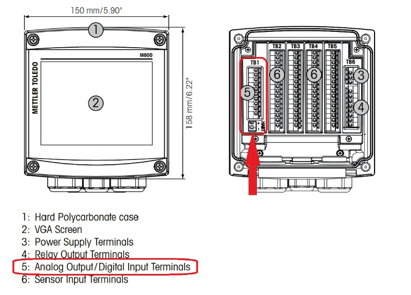
Wiring and Physical Connections
Each instrument and data logger will require different wiring connections that the user will have to determine from the manufacturer or user manual.
A few examples are that an Aber biomass probe uses terminals that bare wire is inserted into, and then a small screw is tightened down to compress and hold the wire in place. Mettler-Toledo transmitters will also have the same thing – bare wire into a press or screw terminal.
A data recording device on the receiving (or input) end, such as a Lascar USB stick, also requires screw terminal blocks. Other instruments — such as Sartorius or Finesse bioreactors — may require specific threaded connectors, like M12s, which would mate to that type of equipment. It will be important to check the correct connector type with the manufacturer and obtain a cable that is able to connect to that specific brand equipment. Please feel free to reach out to PROAnalytics here, as we have lots of experience guiding customers to the appropriate solutions.
Configuring Analog Output on Instruments for Precise Critical Quality Attributes Transmission
Mettler-Toledo M800 Transmitter and Aber Futura Connect Hub
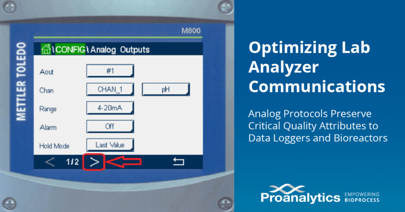
Here are a few common instruments that could act as your analog output. This next section shows you how to navigate through the menu structures and provides some examples: Mettler-Toledo M800 Transmitter:
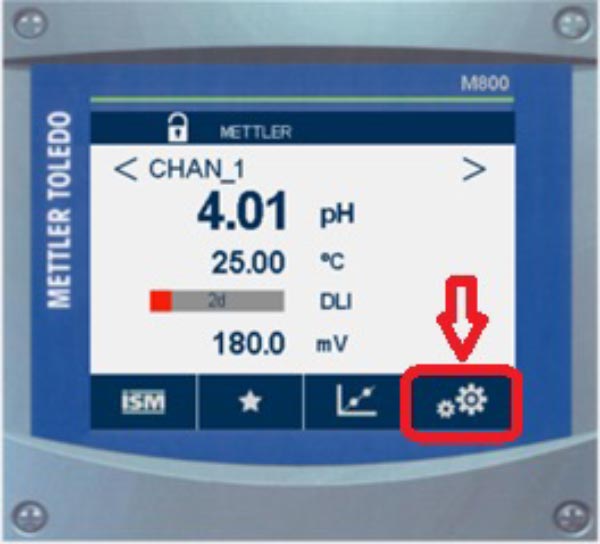
Hit the Configuration button to get started
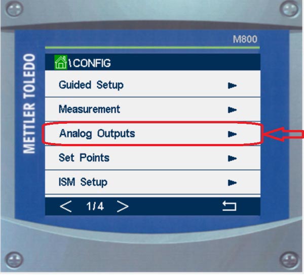
Next, hit the Analog Outputs menu button
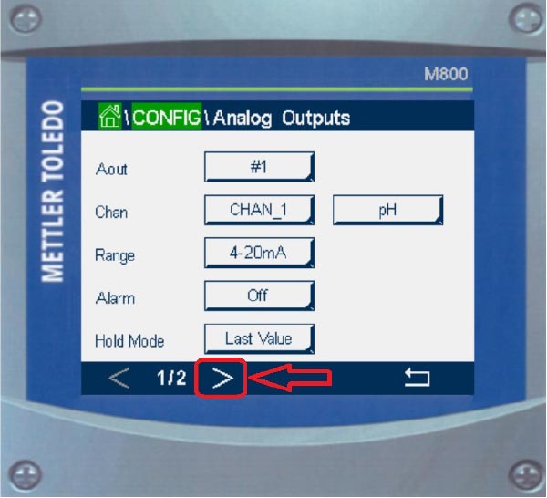
Here, the user can:
- Check that they are configuring the correct channel (i.e. which of the sensors that are connected to the Mettler M800 Transmitter)
- Assign the analog output to the correct terminal location (for physical wire connection)
- Select either 4-20mA option or 0-10V (a nice feature that this transmitter is capable of both options)
- Set the alarm modes
- If you’d like to, you can hold the last value during the times that the measurement is interrupted (such as during calibrations, etc.). This way, the receiving PLC or other equipment does not artificially enter into alarm mode.
Then, select the right arrow to go to the second page.
Note that a Mettler pH probe is often able to measure temperature and also Oxygen Reduction Potential (ORP). Those additional measurement parameters from the same probe can be configured to be output from the M800 on a different pair of terminals, sending those values to the data recorder / PLC / bioreactor controller.
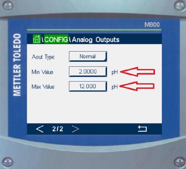
Here on this screen is where you enter the process scaling values, which are the minimum and maximum values that were discussed earlier.
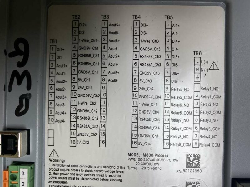
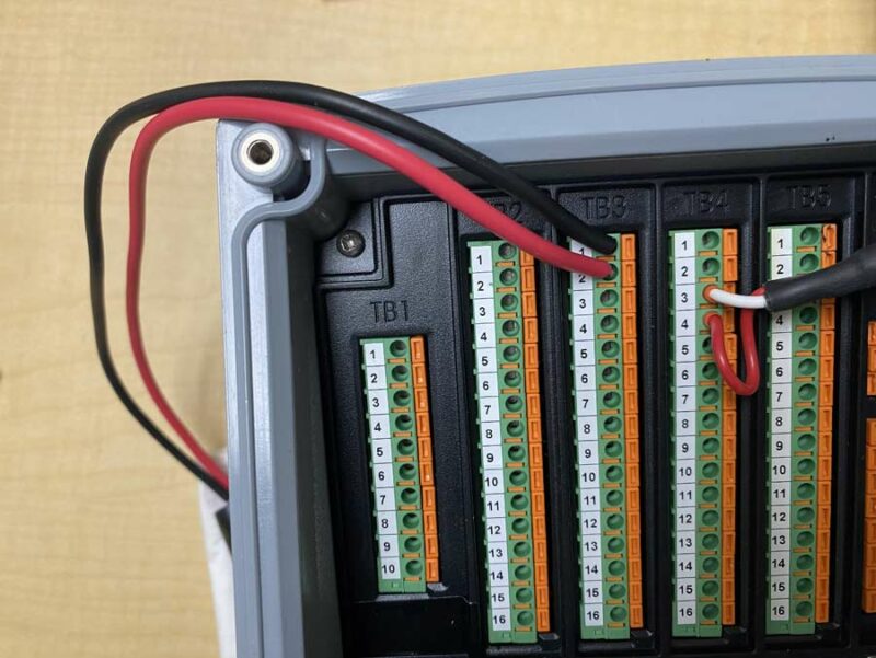
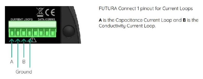
The below image shows where the wires should be physically connected inside of the M800 transmitter:
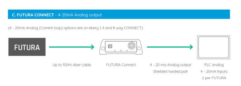
Aber Futura Connect Hub
The use of Aber’s free Futura Tool software, running on a laptop or PC, is used to configure the device. Simply connect the USB cable and click to connect to the device once inside of the software.
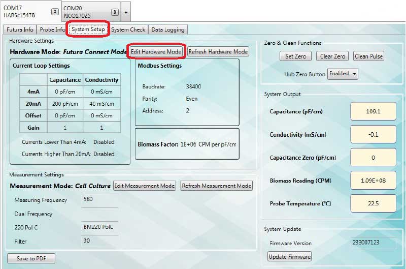
At the very top of this graphic, you can see that two Aber probes are connected: COM17 and COM20. Simply make sure that you are on the correct tab corresponding to the correct probe that you’d like to configure.
Next, navigate to the third subtab called System Setup. Once there, select Edit Hardware Mode. That will bring up the following screen:
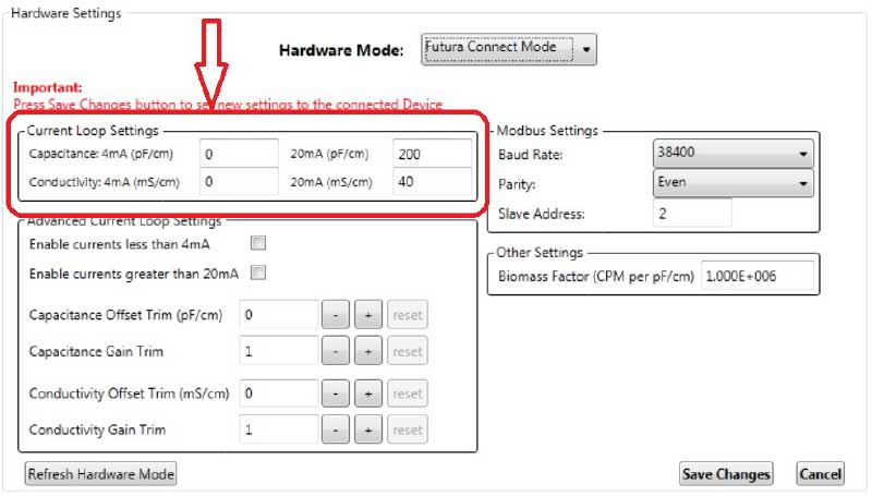
You can see that the Aber probe measures both Capacitance (biomass) and Conductivity (chemical changes within the process). Both of these parameters can be output by the Aber Connect Hub on separate pairs of terminals. One pair of wires will carry the Capacitance signal to the data recorder and another pair will transmit the Conductivity data.
On this screen, you simply enter in the “process scaling” values, which are the lowest and highest values that were discussed earlier in this tutorial.
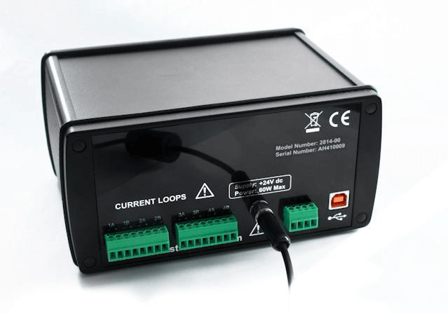
The following will show where the physical wires are connected to the Aber Connect Hub (transmitter).
Testing and Troubleshooting the System with Data Loggers in Mind
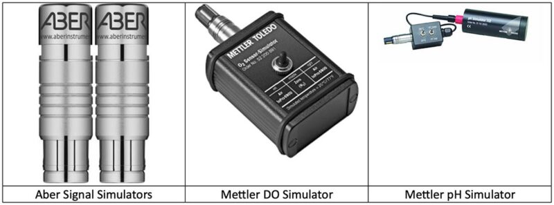
Once everything is physically connected and configured via the transmitter display or software, the next step is to test the system to assure it operates properly. In many cases, instrument manufacturers are able to supply signal simulators, where the probe is removed and a simulator is connected to the transmitter. The purpose of this is to help troubleshooting and to automatically simulate a specific reading for the system. It’s crucial to integrate data loggers effectively during these testing phases.
For example, if you placed a 7pH simulator and a 9pH simulator onto the transmitter, you could read the value on the PLC display to assure it matches the expected value. Here is where some tweaking or troubleshooting might be done.
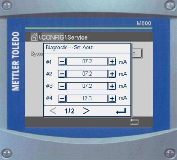
Alternatively, some instrument manufacturers allow the transmitter to simply output a user-defined value in V or mA. This makes testing and troubleshooting the system very easy and convenient. On the Mettler Transmitter, enter into Service mode. From here, you can enter the value that you’d like the transmitter to generate and transmit:
Analog Comms Calibration and Adjustments for Precise Measurement of Critical Quality Attributes
If a user notices that the readings are almost right, but off by a small margin, there could be some loss in the cable. This can be corrected with an analog output calibration. This is performed in terms of a gain (where every value is multiplied by some percent correction) or with an offset (where every value would be adjusted higher or lower by some certain value), ensuring precise measurement of critical quality attributes:
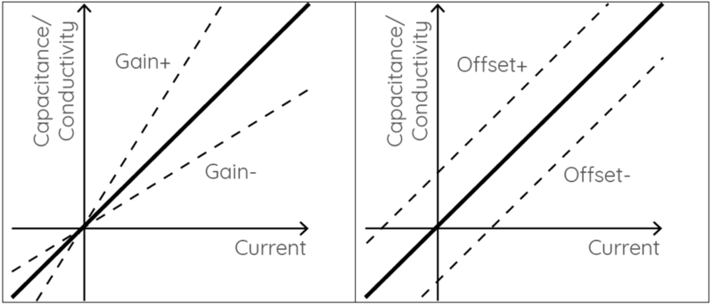
Here is where those settings are entered on an Aber biomass system:
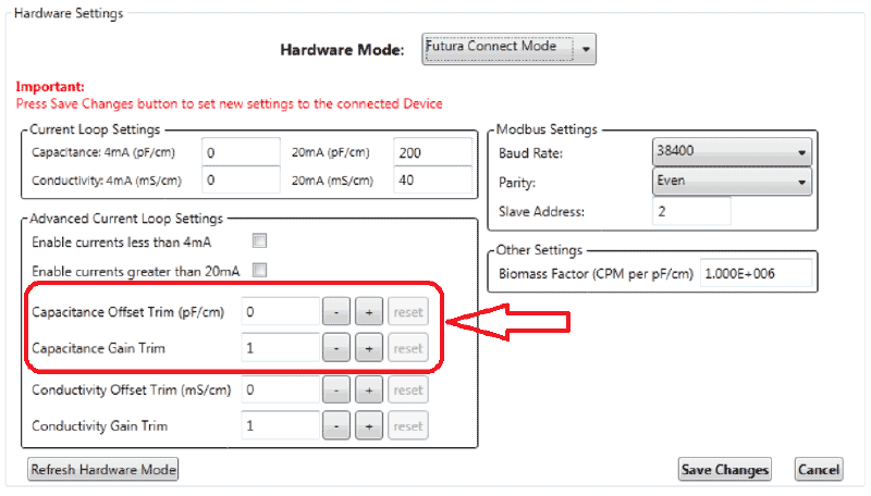
Addressing Unique Circumstances for Seamless Data Logger Integration
If an instrument has only the 4-20mA output and the receiving device has only a 0-10V input option, then a simple resistor can be used to convert from 4-20mA to 0-10V. Please contact us if this issue occurs so we can walk you through this.
Conclusion: The Role of Analog Communication in Enhancing Critical Quality Attributes Monitoring and Data Logging in Bioprocessing
Establishing communication from a laboratory or process analyzer is quite essential for data logging, data centralization, and making real-time automation decisions and control loops based on critical quality attributes. Digital communication protocols exist and have their advantages. However, due to their complexity in nature to set up, this guide will not explain the specific ways to configure a digital communication protocol.