Reports
How Do ProA Flow Sensors Communicate To Allow Automation?

Jun
ProA Flow Sensors are ultrasonic clamp-on flow sensors that measure the flow rate to enable various applications. Integrating flow rate measurements into your existing process is key in automating these applications. For automation, ProA Flow Sensors use digital and analog communication protocols.
Analog communication options:
- 4-20 mA
- 0-20 mA
- 0-24 mA
- 0-10 V
- 0-5 V
- 0-20 kHz
Digital communication options:
- Modbus RTU over RS485
- The use of the ProA Flow Sensor with the Flow Viewer Software through USB conversion
- Digital output options: PNP, NPN, push-pull
- Digital input for sensor control by third-party controllers
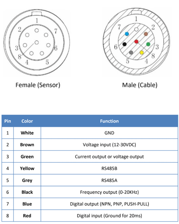
Sensor Output and Cable Output Diagram
ProA Flow Sensors have 8 outputs which are connected to the pins of flow sensor cables. The diagrams for both are below.
Analog Communication Options
Current Output for the Flow Rate
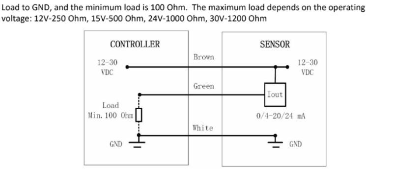
Analog communication is a very popular choice due to the ease of implementation and being a widely accepted protocol to receive data from various sensors. ProA Flow sensors can send various current output options: 0-20 mA, 4-20 mA, 0-24 mA.
To enable the current output option, the sensor is configured for the current output and the desired option is chosen. 0 mL/min is configured for the minimum current output value and the maximum current output value is configured per the user application. The higher the configured the flow rate for the maximum current output, the lower the resolution. This configuration can be selected or modified before the sensor shipment at the factory, by the ProAnalytics service team onsite or by the user if the user has the USB converter to use it with the Flow Viewer software from ProAnalytics.
The electrical connections for the current output are shown below. Please note that the minimum load resistance needed between the current output node and the ground varies with the supply voltage for the flow sensor. Supply voltage can vary between 12V – 30 V. If the user uses the USB converter to power the sensor, 12V is supplied to the sensor. Please check your controller specifications for third-party electrical requirements and more information on load resistance requirements.
Voltage Output for the Flow Rate
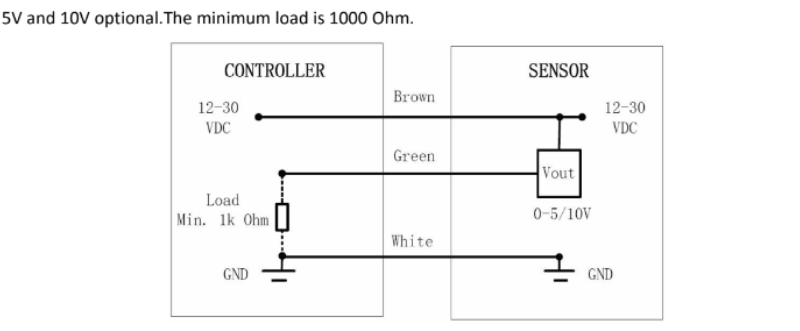
Another analog communication option is the voltage output. The two variations are 0-5V and 0-10 V. Similar to the current output option, to enable the voltage output option, the sensor is configured for the voltage output and the desired option is chosen. 0 mL/min is configured for the minimum voltage output value and the maximum current voltage value is configured per the user application. The higher the configured flow rate for the maximum current voltage, the lower the resolution. This configuration can be selected or modified before the sensor shipment at the factory, by the ProAnalytics service team onsite or by the user if the user has the USB converter to use it with the Flow Viewer software from ProAnalytics.
The electrical connections for the voltage output are shown below. Please note that there is a minimum load resistance needed between the voltage output node and the ground. Supply voltage can vary between 12V – 30 V. If the user uses the USB converter to power the sensor, 12V is supplied to the sensor. Please check your controller specifications for third-party electrical requirements and more information on load resistance requirements.
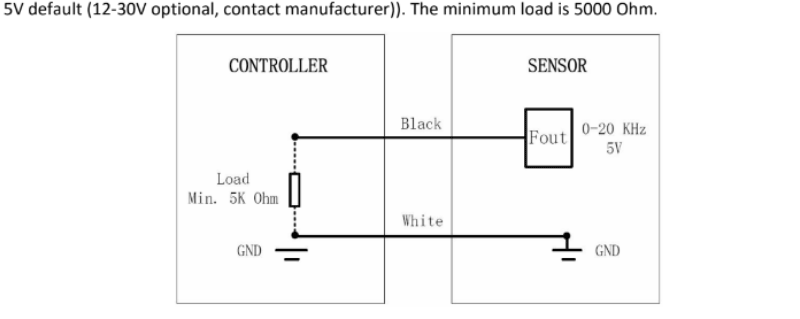
Frequency Output for the Flow Rate
A less common output option is the frequency output with the range of 0-20 kHz. It is very similar to the current and voltage output options in terms of configuration and the use. Minimum load is 5 kOhms. Please check your controller specifications for third-party electrical requirements and more information on load resistance requirements.
Digital Communication Options
Modbus RTU over RS485
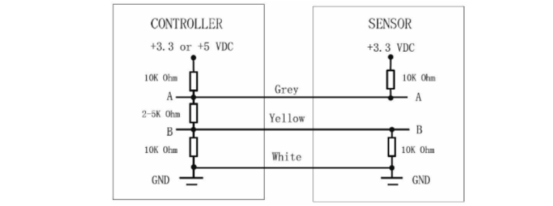
Modbus is a very popular digital communication protocol due to being widely accepted by various control devices and sensors. ProA Flow Sensors enable Modbus data sent through the RS485 cable. RS485 is a very common electrical standard for data transmission. The RS485 interface biasing network is shown below.
Please check your controller specifications for third-party electrical requirements and more information on biasing. Please use baud rate 115200, 8-bit Modbus data with 1 start bit and 1 stop bit, and no parity check. The data arrangement and alignment in the sending and receiving packets can be found in the standard Modbus protocol. The default address of each sensor (device) is 0x04. The sensor supports bus operation with 12 subscribers. ProAnalytics provides the full Modbus protocol upon request.
Modbus Links
- General Introduction to Modbus: http://www.modbus.org/docs/Modbus_over_serial_line_V1_02.pdf
- Modbus Parser: http://modbus.rapidscada.net/
- Modbus CRC Generator: https://www.lammertbies.nl/comm/info/crc-calculation.html
Digital Output Options (NPN, PNP, Push-Pull)
NPN, PNP and push-pull outputs can be configured to provide flow switch, air detection, dosing or pulse output modes. Only one of the output options can be enabled at a time with one of the modes listed. Maximum output is 100 mA.
The Use of ProA Flow Sensor with the Flow Viewer Software through USB Conversion
The easiest way of communicating with the sensor is to use it with the Flow Viewer Software from ProAnalytics. This software is free of charge. In order to use the sensor with the software, USB converter or Flow Sensor Tool Box needs to be purchased from ProAnalytics. Please contact ProAnalytics for more information. This option is suited for stand-alone use of the sensor or enabling the capabilities of Flow Viewer Software along with the analog or digital communication options listed in this document.
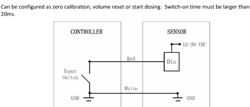
Digital Input for Sensor Control by a Third-Party Controller
The sensor can receive digital input in order to enable zero calibration of the sensor, volume reset or dosing start by a third-party controller. The switch-on time of the controller must be larger than 20 ms.